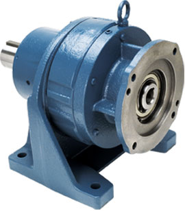
 The Circulute 3000 (ER) series is the ideal choice when requiring a robust gearbox in a compact package. The cycloidal design provides a large amount of contact surface area between the wheel and the pins that allows it to handle unstable loads well and minimize wear. This is our standard cycloidal series providing a variety of frame sizes (A – F) that can handle a maximum input of 60 HP, and also the possibility to implement multiple reductions when required.
There are a number of mounting options available, such as the following;
Input Mounting Configurations:
NEMA C-face with quill style input, Input shaft mount, Structural mounts such as a “Top Mount” and “Shovel Base Mount”, etc.
Output Mounting Configurations:
Base Mount, Flange Mount, Ring Mount, and Horizontal or vertical shaft.
Nidec Drive Technology Corporation can also provide customized features for specific manufacturing environments. These features usually involve a minor changes to the seals, lubricant, the paint or coating applied, materials of construction, etc. Some examples of these special environmental conditions would be;
- IP65 or Heavy Washdown
- Extreme High or Low Temperature Conditions
- Food Grade Critical Exposure
- Among others
The Circulute 3000 can be kit build at our Itasca, IL facility or assembled by some regional certified build centers for fast delivery. From our assembly locations in North America, we can quickly provide most of the common frame sizes and ratios utilized throughout industry today. Contact Nidec DTC for immediate support and information about pricing and availability.
Model Codes | Selection Procedures | Performance Specifications | Dimensions
Selection Procedure for Induction Motor Applications
- Determine the load classification from the Load Classification Table.
- Select the Circulute 3000 Reducer service factor from the Service Factor Table (below) for the application taking into consideration the load classification, duration of service, and type of prime mover.
- Calculate the required reduction ratio by dividing the input shaft rpm by the required output shaft rpm.
- If selecting the reducer by HP, determine the design HP by multiplying the motor HP by the service factor. If selecting the reducer by torque, determine the design torque by multiplying the required load torque by the service factor.
- Select the Circulute 3000 Reducer frame size from the following Selection Performance Specification Tables, making sure that the catalog rating exceeds either the design HP and/or design torque.
- Select the required input type from the Model Codes.
- Select the required mounting type from the Model Codes.
- Select the required mounting position from Model Codes.
- Check the overhung and/or thrust loads on shafts if connected to the load by either a sprocket, sheave, pulley, or gear on the following Dimensions.
- Configure the model number, noting any unusual operating or ambient conditions. Contact Nidec DTC Customer Service for questionable items, or applications assistance.
Service Factor Table
| Prime Mover | Duration of Service | Load Classification | |||||
|---|---|---|---|---|---|---|---|
| Uniform (U) | Moderate Shock (M) | Heavy Shock (H) | |||||
| AGMA | Circulute | AGMA | Circulute | AGMA | Circulute | ||
| Electric Motor | Occasional: 1/2 hour per day | 0.50 | 0.50 | 0.80 | 0.80 | 1.25 | 1.20 |
| Intermittent: 3 hours per day | 0.80 | 0.80 | 1.00 | 1.00 | 1.50 | 1.35 | |
| Up to 10 hours per day | 1.00 | 1.00 | 1.25 | 1.20 | 1.75 | 1.50 | |
| 24 hours per day | 1.25 | 1.20 | 1.50 | 1.35 | 2.00 | 1.60 | |
| Multi-Cylinder Internal Combustion Engine | Occasional: 1/2 hour per day | 0.80 | 0.80 | 1.00 | 1.00 | 1.50 | 1.35 |
| Intermittent: 3 hours per day | 1.00 | 1.00 | 1.25 | 1.20 | 1.75 | 1.50 | |
| Up to 10 hours per day | 1.25 | 1.20 | 1.50 | 1.35 | 2.00 | 1.60 | |
| 24 hours per day | 1.50 | 1.35 | 1.75 | 1.50 | 2.25 | 1.70 | |
| Single Cylinder Internal Combustion Engine | Occasional: 1/2 hour per day | 1.00 | 1.00 | 1.25 | 1.20 | 1.75 | 1.50 |
| Intermittent: 3 hours per day | 1.25 | 1.20 | 1.50 | 1.35 | 2.00 | 1.60 | |
| Up to 10 hours per day | 1.50 | 1.35 | 1.75 | 1.50 | 2.25 | 1.70 | |
| 24 hours per day | 1.75 | 1.50 | 2.00 | 1.60 | 2.50 | 1.80 | |
Note: AGMA service factors shown are the American Gear Manufacturers’ recommendations for conventional gear reducers.
Miscellaneous Engineering Information
Ambient Temperature
The ambient operating temperature range of the Circulute 3000 Reducer is from 32oF to 104oF (0oC to 40oC). Contact Nidec DTC Customer Service if operating conditions fall outside of this range.
Backlash
The standard backlash option is approximately 1° (60 arc-min). The precision backlash option is less than 0.1° (6 arc-min).
Direction of Rotation
The input shaft can be rotated in either direction. For single reduction reducers, the output shaft rotates in the opposite direction of the input shaft. For double reduction reducers, the output shaft rotates in the same direction as the input shaft.
Exact Ratio
All Circulute 3000 reduction ratios listed in this catalog are exact.
Thermal Ratings
The high efficiency of the Circulute 3000 Speed Reducer results in thermal ratings which exceed its mechanical rating in all cases. Therefore, it can be run continuously at any of the input speeds in this catalog.
Table 1 Input Shaft Thrust & Overhung Load Capacity (lbs)
| Frame Size | Load Type | Input Shaft Speed (rpm) | |||
|---|---|---|---|---|---|
| 580 | 870 | 1165 | 1750 | ||
| A | OHL Thrust | 260 | 260 | 230 | 200 |
| 130 | 130 | 115 | 100 | ||
| B | OHL Thrust | 260 | 260 | 230 | 200 |
| 130 | 130 | 115 | 100 | ||
| C | OHL Thrust | 400 | 390 | 350 | 310 |
| 200 | 195 | 175 | 155 | ||
| D | OHL Thrust | 600 | 600 | 540 | 480 |
| 300 | 300 | 270 | 240 | ||
| E | OHL Thrust | 1,300 | 1,100 | 1,000 | 880 |
| 650 | 550 | 500 | 440 | ||
| F | OHL Thrust | 1,700 | 1,500 | 1,300 | 1,200 |
| 850 | 750 | 650 | 600 | ||
Notes: Overhung load ratings are based on the load being applied to the center of the shaft.
Ratings shown are based on a combined overhung and thrust load being applied to the shaft.
Output Shaft Overhung Load
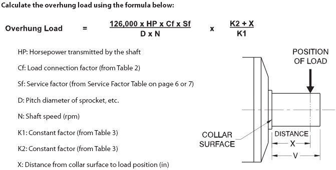
When a sprocket, sheave, pulley, or gear is mounted on the output shaft or on the input shaft, an overhung load is applied to the shaft. It is necessary to check whether the shafts of the reducer will allow the required overhung load.
Overhung Load Calculation

Table 2 Load Connection Factor: Cf
| Type of Connection | Factor |
|---|---|
| General Purpose Chain | 1.00 |
| Machined Gear, Pinion, or Syncronous Belt | 1.25 |
| V-Belt | 1.50 |
| Flat Belt | 2.50 |
Table 3 Output Shaft Overhung Load Capacity (lb)
| Frame Size | Output Shaft Speed (rpm) | Constant Factor | |||||||||
|---|---|---|---|---|---|---|---|---|---|---|---|
| 40 & Below | 50 | 60 | 80 | 100 | 125 | 150 | 200 | 250 & Above | K1 | K2 | |
| A | 780 | 780 | 780 | 780 | 780 | 764 | 715 | 650 | — | 5.37 | 4.67 |
| B | 1,284 | 1,284 | 1,284 | 1,284 | 1,284 | 1,268 | 1,186 | 1,073 | 934 | 5.67 | 4.67 |
| AB | |||||||||||
| C | 2,763 | 2,600 | 2,438 | 2,275 | 2,113 | 1,950 | 1,788 | 1,625 | 1,414 | 6.83 | 5.55 |
| AC | |||||||||||
| D | 5,038 | 4,713 | 4,550 | 4,063 | 3,738 | 3,575 | 3,250 | 3,088 | 2,687 | 8.26 | 6.38 |
| AD, BD | |||||||||||
| E | 7,475 | 7,475 | 7,475 | 7,475 | 7,313 | 6,825 | 6,338 | 5,688 | — | 11.4 | 9.25 |
| BE, CE | |||||||||||
| F | 12,188 | 12,188 | 11,538 | 10,563 | 9,750 | 9,100 | 8,613 | 7,800 | — | 13.9 | 11.1 |
| CF, DF | |||||||||||
Notes: These ratings are based on thrust load = 0.
Contact Nidec DTC Customer Service for applications which have combined overhung & thrust loads.
